–HEBEI CHENGDA PIPES CO., LTD

Section 1
Installation Instruction
- Correct handing and installation are vital to the safe use of membrane housing and their components and long service life. Please read and understand all guidelines given before attempting to open, service or operate Winder® FRP membrane housing.
Note: This pressure vessel may cause severe bodily harm, and/or explosive head failure if not correctly installed, operated and maintained.
- We recommend that only qualified mechanics, experienced in servicing high pressure hydraulic systems, open, close and service this vessel to avoid potential or potential safety hazards.
- However, they do not relieve the user from full responsibility for correct operation and maintenance of the vessels. Damage due to improper handling or installation is the sole responsibility of the purchaser.
Section 2
Installation Steps (Illustrate by side port)
- Mounting shell
- Fix the FRP membrane housing on the center of the frame with saddles and flexible straps.
Note: Provide adequate clearance for servicing at both ends of the vessel. Try to align the feed port and concentrate port. Assure that each vessel be placed to minimize strain on piping that connects a vessel to a header.
- Assure that saddles and straps leave space for the expansion of the shell. The bolts used should not be so tight.
- Mounting design must allow for vessel expansion, both axially and radically. Although the expansion under pressure is slight. However, if the expansion is restricted, it may cause damage to the vessel and other system components.
- Fix the FRP membrane housing on the center of the frame with saddles and flexible straps.
- Cleaning
Remove the housing head, rinse away all loosened deposits from each components and the housing inside surface using clean fresh water or a mild solution.
- Lubricating
Using glycerine to lubricate the head sale set, adapter seal area and also applied uniformly on the slope of the groove in the head. To ensure that the seals can be smoothly pushed forward.
- Element loading
- Load the first element from feed port (inlet side) to concentrate port (outlet-side).
Note: The membrane element must always be installed from the inlet of the membrane housing, reverse installation may result in damage to the seal set of concentrate port.
- Assemble the inter-connector O-ring covered with glycerin to the loaded element. Repeat loading process until all elements are installed.
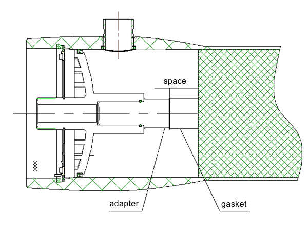
- When the final element is installed, push the element stack forward until the distance between the downstream element and retaining ring groove is about 180 mm.
- Install the adapter with glycerine of concentrate port into the membrane permeate tube.
Note: Install the membrane housing from the inlet side. Take care to avoid pushing the final elements too far as it can be difficult to push the stack in a reverse direction.
- Load the first element from feed port (inlet side) to concentrate port (outlet-side).
- Concentrate port installation
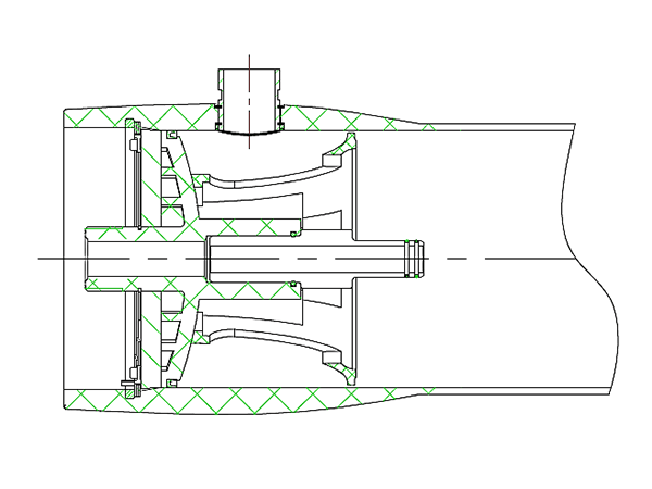
- Install the permeate port seal with glycerine and bearing plate on the permeate port, then place retaining ring into the retaining groove to form permeate port set.
Note: Remove the excess glycerine on the adapter.
- Insert the permeate port set slowly and vertically into the thrust cone to ensure the two ribbed slab is in the groove.
- At the concentrate port, push the permeate port set and thrust cone vertically into the inside of three turns locking ring groove. Head can be tapped lightly with rubber mallet if necessary to seat the head into position.
- Install the permeate port seal with glycerine and bearing plate on the permeate port, then place retaining ring into the retaining groove to form permeate port set.
- Locking ring installation
Install three turns locking ring. Pushing three turns locking ring into the groove as you rotate your hand three times until the entire three turns locking ring is installed in the groove. And then install the security bolt with the inner hex wrench.(important)
Note: Three turns locking ring must be installed correctly. Failure to install it will cause head explosion under pressure.
- Feed port installation
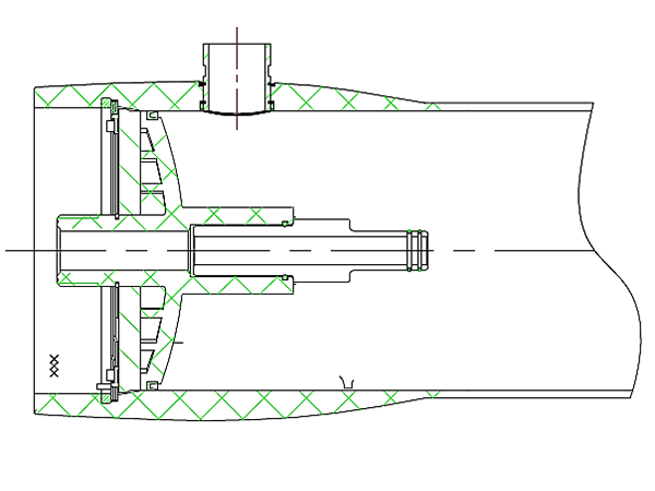
- The installation of feed port is the same to the concentrate port.
Note: Do not install thrust cone at feed port.
- Check feed port head assembly and use a rubber mallet to tap the bearing plate of feed port to assure no leak between adaptor and permeate pipe. If there is leak between adaptor and pipe, please use the PPR washer provided by Winder® to relieve it.
Note: Avoid over strength on strew plug to prevent any damage. Ensure PPR washer is correct installation, avoid movement of membranes to prevent striking the head is assembles into the vessel, and protecting membranes are well. A washer must be installed on the adapter that is connected between the shell and the element to eliminate the installation leak.
- The installation of feed port is the same to the concentrate port.
Section 3
- Pre-pressure check
To avoid any installation omission and improper operation, the following items shall be checked and verified:
- All the spare parts according to the list. Whether there is debris left in the membrane housing to avoid the back pressure damage membrane element and membrane housing.
- The proper installation of permeate port and bearing plate.
- Retaining ring is properly in place.
- Thrust cone is installed at downstream end of vessel. Prevent damage to the membrane element during backwashing.
- Check all piping connections to ensure the installation is in place.
- Pressurization
After completing the above pre-pressurization checks. Vessels should be filled slowly to assist trapped air in escaping. After emptying then relieve pressure, go over it one more time to prevent water hammer and make sure the sealing ring is relaxed and reducible.
Note: Please do not pressurize the vessels before pre-pressurization checks. System damage and bodily harm caused by failure to follow above guidelines is the sole responsibility of the purchaser.
Section 4
Removing head assembly
- Relieve pressure. Shut off all sources of pressure and relieve pressure from the shell.
- Disconnect and remove feed/concentrate port and water outlet pipe.
- Remove the three turns locking ring from the groove inside the shell, following the procedure: first, use hexagon square spanner disconnect the screw, Use the rubber hammer to tap the bearing plate to loosen the retaining ring, raise the head of the locking ring and move it out of the groove, rotate the retaining ring three times until you pull it out completely.
- Remove permeate port assembly.
- The disassembled parts should be arranged in order to avoid the shortage of parts when they are reinstalled.


